Created by Subhashini Rajendran
Today every building has a minimum of 5 floors. It is highly expensive and difficult to manually turn ON/OFF the lights in each rooms, corridors, floors, steps, etc. It is also expensive to manually adjust the amount of lighting according to the availability of sunlight in that particular area.
So, lighting control systems are installed in buildings that automatically control the amount of light and availability of light.
One such widely used system is DALI
DALI is Digital Addressable Lighting Interface. In simple terms, DALI is a two – way communication system that digitally controls lighting. It is a communication medium between the user and the light ballasts (or the LED light panels). The ballasts are the current limiting devices, just like the one used in the common domestic fluorescent lamps.
Created by Subhashini Rajendran
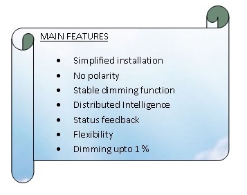
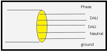
In DALI lighting system, each individual device has only 2 hardwires, one for input and the other for digital control. Controls are wired using the same type of standard wire as is used for power.
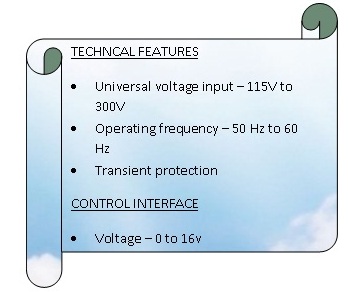
Up to 16 different light levels, rates, and fade times can be implemented. DALI allows lighting controls to be done by PCs by using software.
It is also endowed with automatic identification of failed lamps and ballasts.
WORKING OF DALI
Each and every ballast has separate address and each DALI loop can support 64 individual addresses. DALI’s main function is to communicate between the light panel and the user.

Created by Subhashini Rajendran
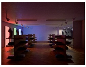
Figure 1 DURING THE DAY
Created by Subhashini Rajendran
Figure 2 AT NIGHT
DALI sends messages to the ballasts via addresses. The ballast with that address takes it and follows the instruction. For example, the message would be “Turn OFF all lights in room 2”.
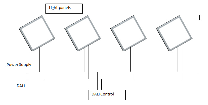
DALI with light panel
Each DALI control acts as a master. The light panels are the slaves. The DALI control unit sends command “scene 1”. The processor takes up the task of setting the scene. The processor now compares the lighting value of scene 1, which has been stored in its internal register with the current value. The difference between the values is calculated. According to the difference the current to the panel can be controlled.
Created by Subhashini Rajendran
Created by Subhashini Rajendran
DALI can query the status of the ballast in the light panel.
Components used to install DALI
Voltage supply
In general the system voltage is 16V, ranging from 9.5V to 22.4V.
A master control
There can be single master controller or many controllers. However, when many controllers are used for a speedy response, traffic of the signals has to be taken care.
Selection of connecting wires
Cables and wires of commercial installation can be used. The maximum voltage drop allowed across the connecting wires is 2V. The main rule is that the distance between two communicating units should not exceed 300m.
Ballasts and light panels
An interface line can connect up to 64 addresses of panels.